
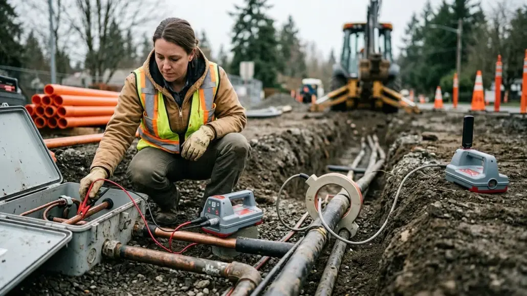
Cable and pipe locating systems commonly offer three active signal application methods. What changes in the field is how much control the operator has over the conductor carrying that signal.
When comparing systems in UCG Underground’s Radiodetection collection, buyers should look beyond the receiver name. The transmitter, leads, and compatible clamps determine which methods the crew can actually use.
Direct connection usually provides a controlled starting circuit. A clamp gives access without exposed electrical contact. Broadcast induction helps when access is unavailable, but requires more caution about target identity. None of the three automatically proves which utility has been found.
Three methods, one receiver—and different signal paths
An active electromagnetic locate follows current on a conductor. The receiver interprets the resulting field, so signal application is part of the measurement system.
| Method | Required access | Main purchasing advantage | Main operating limitation |
| Direct connection | Approved electrical connection point on a known conductor | Control of the initial signal circuit | Poor contact, continuity or return path can undermine the trace |
| Transmitter clamp | Space to enclose the intended conductor | Signal application without exposed contact | Exact clamp compatibility and a usable circuit remain necessary |
| Broadcast induction | Surface access near the search area | Search without reaching the utility | Nearby conductors and airborne transmitter pickup can complicate identification |
A practical field comparison of direct connection, clamp and induction develops these trade-offs by access and signal path. It is more useful to evaluate them as choices within a workflow than to label one method universally superior.
Direct connection: control the circuit before adding power
Where safe, authorized access exists, direct connection lets the operator apply the signal at a known point. Radiodetection identifies it as the preferred method in many applications.
The important procurement consequence is that leads and ground accessories are working equipment. Their condition belongs in the acceptance check. A receiver demonstration performed with a complete supplier kit may tell little about a purchase that omits those components.
A poor circuit can create a weak trace even with a capable transmitter. Before assuming that more output is the answer, the crew needs to evaluate the connection and return path using the applicable manual and utility-owner procedure.
Safe access also defines the method’s boundaries. Connecting to an energized conductor requires qualified personnel and the appropriate approved products. Use the approved connection procedure and accessories for the energized system.
Direct connection improves control at the application point. Shared bonds and other current paths can still distribute the signal beyond the intended conductor.
Signal clamps: selective application with compatibility limits
A transmitter clamp applies the signal around an accessible conductor without requiring exposed contact. That can make it practical where a direct connection is unavailable.
The conductor still needs a usable circuit. Radiodetection notes that grounding or sufficient capacitive coupling can affect signal transfer. Closing the clamp around a cable does not by itself demonstrate that the signal will travel usefully along the route.
Check jaw closure, cable condition, connector and part number. A gap in the clamp’s magnetic core can interfere with transfer. A clamp that appears undamaged should still be tested with the intended transmitter.
Compatibility extends beyond diameter. Radiodetection’s listed standard transmitter clamps support 8–200 kHz; that specification applies to those accessories, not every clamp sold for utility locating. Current Direction applications require the appropriate CD clamp and compatible system frequencies.
Transmitter and receiver clamps have different jobs. Buying a receiver identification accessory does not add a transmitter signal application method.
For live insulated power cables, follow the precise manufacturer and utility-owner requirements. Radiodetection warns against clamping uninsulated live conductors and specifies that the clamp remain connected to the transmitter when applied or removed around a power cable.
Broadcast induction: valuable access, weaker identity evidence
Induction lets the crew search without physically reaching the conductor. This is an important capability when the route or an access point is unknown.
Its trade-off is less control over which nearby line receives the signal. Several conductors may respond. The receiver can also pick up the transmitter directly through the air.
That creates a buying question: can the proposed system support a deliberate search and then a more controlled trace? A kit that depends entirely on surface induction may leave the crew with insufficient options when a congested site produces conflicting routes.
Demonstrations should include a change of transmitter position and application method where practicable. A response that appears only near the transmitter needs investigation; it should not become a confidently marked utility simply because the display is strong.
Why a convincing signal can still follow the wrong line
Parallel conductors can carry part of the same locating signal through coupling, shared bonds or return paths. The receiver then interprets a combined field.
The explanation of how parallel utilities distort locator readings describes why a clean-looking peak and plausible depth can coexist with wrong-line identification.
For equipment evaluation, ask the demonstrator to explain discrepancies rather than hide them. Does the route connect with known features? Does another controlled application produce the same interpretation? Can the operator recognize a questionable field?
Current and direction functions add evidence where supported. Radiodetection’s Current Direction requires compatible transmitter and receiver settings and the correct application accessory. It is not a universal identity certificate.
The useful premium is a function the crew can interpret and incorporate into its work. A display feature with no corresponding procedure may contribute little to the decision.
What to ask for in a locator-system quote
Request a configuration sheet, rather than a general statement that the system “supports all methods.”
It should identify:
- Exact receiver and transmitter variants.
- Connection accessories supplied and their condition.
- Clamp part numbers, supported frequencies and usable jaw openings.
- Whether a special clamp is needed for direction functions.
- Any feature that requires a particular transmitter or software configuration.
- An acceptance demonstration using the actual supplied components.
For an existing fleet, compare the new accessory against the equipment already in service. A low purchase price loses its value if the crew cannot use the item with its transmitter.
Used clamps deserve the same functional scrutiny as used receivers. A complete-looking case can still contain the wrong accessory.
Choose by access and verification requirements
Start with direct connection where the known conductor can be reached safely. Consider a compatible clamp where access allows enclosure without an approved contact point. Use induction to address the access gap and search for conductive routes.
Then evaluate whether the evidence supports the target identity. Access determines the starting method; verification determines how much confidence the result deserves.
The right market comparison is therefore between usable systems and procedures. Counting receiver features alone misses the component that creates the signal and the checks that make its interpretation defensible.